SUPER FLUX LED Lighting the Future


| Applications |
|---|
| Automotive Lighting |
| Electronic Signs and Signals |
| Special Lighting Application |
| Model (Emitting Color) |
SF-RSHH red |
SF-RSEE red |
SF-YSHH yellow |
SF-YSEE yellow |
|---|---|---|---|---|
| Power Dissipation | 200 mW | 200 mW | ||
| Peak Forward Current (Duty 1/10@1KHZ)* | 160 mA | 160 mA | ||
| Continuous Forward Current | 70 mA | 70 mA | ||
| Reverse Voltage | 5 V | 5 V | ||
| Operating Temperature Range | -40~+80 ℃ | -40~+80 ℃ | ||
| Storage Temperature Range | -40~+85 ℃ | -40~+85 ℃ | ||
| Lead Soldering Temperature△ | 260 ℃ | 260 ℃ | ||
| Material | AlInGaP | AlInGaP | ||
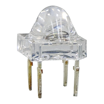
| Lens | water clear | water clear | ||
| Forward Voltage | 2~3 V | 2~3 V | ||
| Luminous Intensity ±20 % | 10,000~17,000 mcd | 13,000~22,000 mcd | 10,000~17,000 mcd | 13,000~22,000 mcd |
| Dominant Wavelength | 618~630 nm | 585~596 nm | ||
| Typical Viewing Angle (2θ1/2) | 45 | 23 | 45 | 23 |
| Typical Electro-Optical Characteristics Curves | 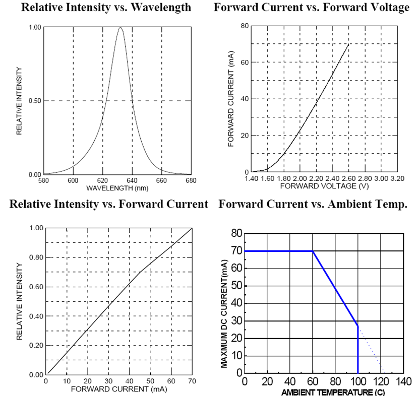 red |
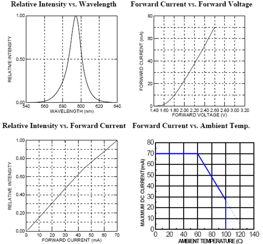 amber |
||
| Hand Soldering | DIP Soldering | Temo. at tip of iron | 400 ℃ Max. (30 W Max.) | Preheat temp. | 100 ℃ Max. (60 sec Max.) |
|---|---|---|---|
| Soldering time | 3 sec Max. | Bath temp. | 265 Max. |
| Distance | 3 mm Min. (From solder joint to case) | Bath time. | 5 sec Max. |
| Distance | 3 mm Min. | ||